What is a Balancing Machine, and How Do Balancing Machines Work?
What Is A Balancing Machine?
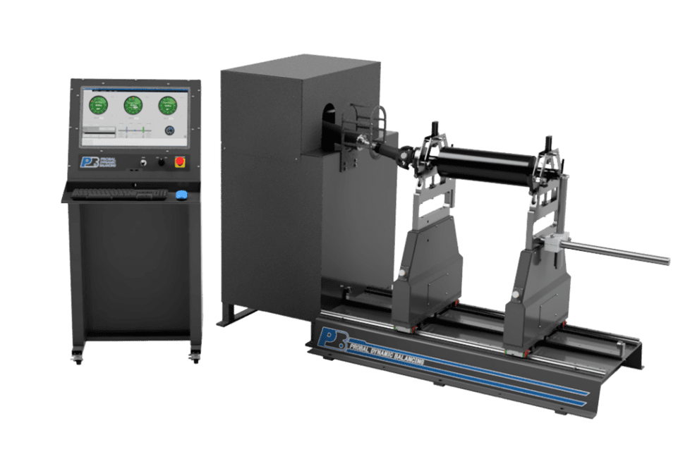
A balancing machine is a piece of equipment which rotates a cylindrical part, measuring the amount of unbalance present, then informs the operator of the location of the unbalance and the mass to be added to the rotor to get it back to a balanced state.
The dynamic balancing machine should have a stable base upon which everything above it can remain as rigid as possible during operation. Columns are then mounted to the base to support the trunnions. The columns should be traversable from side to side to allow for a range of part lengths. Our Probal machines come in modular lengths of five feet long, per module; and are extendable to suit a very wide range of part lengths.
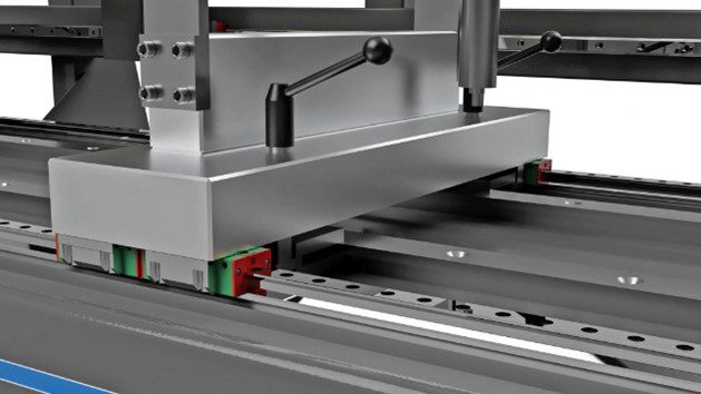
Some of our more common builds have been agricultural auger balancing machines, which have extended out to 25 feet in length. One of the benefits of our balancing machine base designs is our utilization of linear rail bearings between the columns and the base. On longer machines, we use longer linear rail segments (longer than just 5 feet each) to reduce the number of breaks between segments, thereby reducing the chances of rails not being colinear from segment to segment.
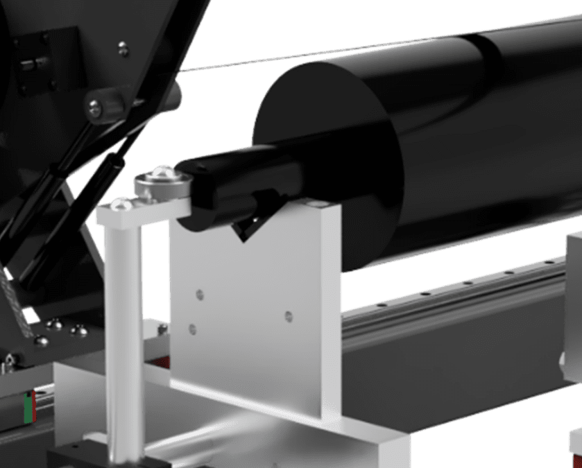
The trunnions come in a variety of configurations containing the bearings, which is what the part itself rests on. For Probal Dynamic balancing machines, we have both fixed and adjustable height trunnions. On top of those options, we also offer a range of bearing styles, from roller bearings to crowned composite v-block inserts. Using inserts allows them to be easily replaceable after long-term wear or damage.
The bearing type is largely what determines the class of the machine. You have hard-bearing machines and soft-bearing machines. All our machines at Probal are hard bearing balancing machines. Soft bearing machines are mounted on a flexible support structure, whereas hard bearing machines utilize a rigid support structure for the part being balanced. The explanation of the difference between hard and soft bearing machines is a topic we have covered in previous articles.
A driving mechanism is supplied to rotate the component at a predetermined speed. We use a couple different means of measuring the rotational speed: a non-contact optical PhotoEye sensor and a rotary encoder which can be connected to either the part or the motor. The PhotoEye sensor works well with parts in which there is no means to attach the rotary encoder to the end of the part itself. In a recent update to our Probal Dynamic Balancing software, we have made it so that the PhotoEye now works in conjunction with the rotary encoder to get the most accurate data possible. The rotary encoder itself has a couple different mounting configurations. It can be mounted directly to the overhead drive system, directly to the end-drive system, or it can attach to the part itself using a u-joint or magnetic mount.
We offer three different types of drive systems: an overhead belt drive, a wrap-around belt drive and a direct in-line drive system.
- Our overhead drive system traverses on its own linear bearing rail behind the part and can be lowered onto the part manually, then allowed to spring return back into its upright position. This method allows for the most versatility and ease of loading/unloading parts onto the machine.
- The wrap-around belt drive system is a more traditional method of driving the part’s rotation. It involves looping the belt over the part during loading and using the adjustable pulley on the drive system to tighten it down around the part. This does also provide an added layer of safety protection as it is essentially holding the part down onto the bearings.
- The direct in-line drive is fairly straightforward (pun intended). The motor drive system is directly in line with the axis of rotation of the part itself. This usually involves some type of adapter to affix the part to the driveshaft of the drive system.
The way in which the machine determines the unbalance is by measuring the vibration signals in the columns as the part is rotating at speed using piezoelectric sensors. As the part rotates, the offset mass (causing the center of mass to deviate from the axis of rotation) creates centrifugal force. This in turn makes the part want to move outward, causing vibration. The vibrational force travels through the trunnions where it is picked up by the piezoelectric sensors. This sensor data is processed and converted into human-readable imbalance results displayed on the screen. Probal balancing machines show you both how much unbalance is present, as well as where the unbalance exists in the part itself.
Not only does the Probal software display the unbalance data relative to the part, but it also displays the correction data needed to alleviate the unbalance, particularly how much material to remove and where. This information provides the fastest means of balancing a large array of parts: from electric motor rotors to large propellers, centrifugal pumps to pump impellers, driveshafts to armatures, and much more.
Probal balancing machines also include standard features such as report generation, saved calibration files, tooling error compensation, automatic calibration, and so on, allowing the equipment to balance rotors as efficiently and quickly as possible for an industrial setting.
Why is a Balancing machine required?
As previously stated, the imbalance is generated by an unequal mass distribution around a rotational axis. Balancing is, therefore, the process of minimizing unequal mass distribution in spinning components by adding or subtracting compensatory mass.
The resulting stress and vibration in the supporting structure caused by an imbalanced rotor is a big issue. This vibration causes premature/ excessive wear or failure of bearings, shafts, bushings, spindles, gears and other components, lowering the component’s service life.
In addition to the detrimental influence on the lifetime of the component, vibration causes other drawbacks and quality difficulties.
Centrifugal forces degrade performance by increasing friction forces in bearings. In addition, as a result of the energy being absorbed by the supporting structure, performance suffers.
Vibrations degrade dependability and can substantially affect a product’s capacity to work correctly.
Returning to the original topic, why is a balancing machine required? Using a balancing machine to measure and fix a rotor’s imbalance will:
- Improve the overall quality of the product, thereby increasing overall value.
- Allow for more efficient power usage.
- Reduce audible and signal noise.
- Lengthen the operating life and minimize downtime.
There are three types of balancing machines:
Balancing machines for universal balancing
- These devices can detect both static and dynamic imbalance.
Balancing machines for dynamic balancing
- These devices solely measure dynamic imbalance.
Balancing machines for static balancing
- These devices solely measure static imbalance.
Characteristics of an Effective Dynamic Balancing Machine
A good balancing machine has the following characteristics:
- High Precision.
- Design that is dependable and consistent.
- Removes or reduces extraneous effects on measurements.
- Calibration is permanent. Therefore, there is no need to recalibrate every use.
- Adaptable to a variety of components.
- Simple to set up and use.
- Repeatable measurements.
- Intuitive user interface.
- Software features which increase productivity and efficiency.
- Excellent client service and support
Balancing Machines ROI
A balancing machine is an investment in your product’s quality. The cost of the balancing machine has only a little impact on the investment’s profitability.
As a result, the following factors should be considered when calculating the return on investment:
- Process performance improvement. The machine should provide a competitive advantage and cost-saving way to result in greater efficiency.
- The time savings not only reduce labor costs, but allows jobs to finish faster.
- Cost savings as a result of shorter unexpected downtimes as well as maintenance schedules.
- Product quality has greatly improved. There are no vibrations or noises, which means more customer satisfaction and a competitive edge.
- The rate at which products fail is reduced.
- Product reputation becomes more dependable.
- Rotating components and assemblies have a longer use life.
Conclusion:
In this article, we have guided you through the basics of balancing machines and their importance at the industry level. We hope all the information was relevant and useful. If you have any questions or would like to inquire about purchasing a new balancing machine or machine upgrade visit our Contact page.


1 comment
Ahmed Ali July 27, 2025
Balancing Machine